 Custom parts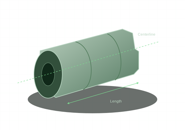
Flat faces and pockets suggest milling. Diameters and shoulders around a common axis suggest turning.
Milling favors accessible faces
A mill uses rotating tools to cut profiles, pockets, surfaces, and hole patterns. Rectangular blocks and plates often fit naturally into this process. Multiple orientations may be needed when important features lie on several sides.
Turning favors axial geometry
A lathe rotates the workpiece to create outside diameters, bores, grooves, and faces. Bushings, shafts, and round spacers are natural candidates. Slender sections and deep bores need attention to support and tool rigidity.
Many parts need both
A round housing with a cross hole or mounting flats may start as a turned component and then require milling. Conversely, a mostly prismatic part may include a precision bore made on a mill. A round feature is not proof that the entire part belongs on a lathe.
Simplify around function
If a feature can share an existing setup without compromising function, it can reduce handling. Keep critical relationships clear on the drawing and avoid adding geometry solely to force one process. KRC’s online CNC workflow evaluates the model; customers do not need to choose a machine type.