 Custom parts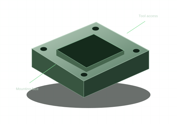
The most useful design improvement often removes a difficult feature without changing the part’s function.
Start with access and workholding
Every cut needs a path for the tool and its holder. Deep internal cavities, hidden undercuts, and features blocked by surrounding geometry can prevent ordinary machining. The part also needs rigid surfaces for clamping without distorting the final geometry.
Use proportionate features
Large internal radii allow larger, more rigid cutters. Shallow pockets are generally easier than deep narrow ones. Thick, short walls are more stable than tall thin walls. These relationships are design principles, not universal shop acceptance limits; material and feature proportions still determine feasibility.
Simplify the setup plan
Group related features on accessible faces and use common hole sizes. Avoid unnecessary angled holes and special tools. Consider whether a complex one-piece part could become a simpler assembly, while checking the added fasteners and alignment requirements.
Define only the precision you need
Use tighter tolerances for fitted and locating features, and general tolerances where function permits. Identify threads and functional surface requirements on a drawing. Release one consistent model-and-drawing revision so the quote describes the part you intend to build.