 Custom parts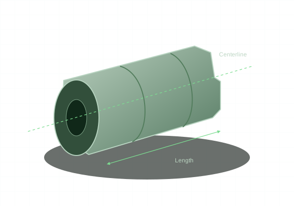
Choose turning when most of the part can be described by diameters and lengths around one axis.
How turning creates the part
The workpiece rotates while a cutting tool generates outside diameters, faces, grooves, and shoulders. Drilling and boring create internal features. Milling may still be necessary for cross holes, flats, or off-axis details. The presence of a round feature alone does not make an entire part a one-operation lathe job.
Give shoulders and bores room
Internal corners reflect the cutting tool nose radius. Mating shafts and shoulders need compatible chamfers or reliefs. A blind bore needs room for the tool to enter and clear chips. State whether a bore depth refers to usable cylindrical depth or the deepest point of a drill tip.
Support slender geometry
Long, small-diameter sections can deflect during cutting. Deep bores can suffer similar rigidity limits at the tool. Shortening unsupported spans and avoiding unnecessary deep reliefs improves stability. A drawing should identify the centerline and the surfaces that locate the part in the assembly.
Define the fit, not just the diameter
A bearing seat or sliding shaft requires a deliberate fit. A general ±0.005 inch dimension is not a universal bearing-fit specification. Put critical diameters, their tolerances, and any required runout relationship on the PDF drawing. Threads also need a full designation and usable length.