 Custom parts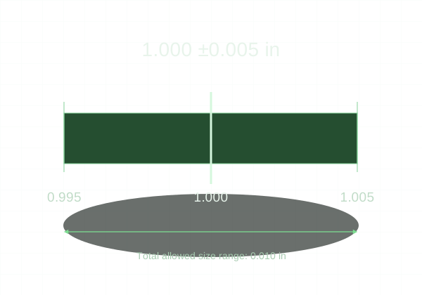
Use ±0.005 inch for suitable general dimensions; apply tighter limits only where the assembly needs them.
KRC’s standard dimensional tolerance
The standard CNC tolerance is ±0.005 inch, equivalent to ±0.127 mm. On a 1.000 inch dimension, that represents an acceptable size range of 0.995–1.005 inches, unless a different accepted requirement governs the feature. This is a dimensional tolerance, not a blanket specification for flatness, surface finish, or positional accuracy.
Tighter online selections
The quote includes tighter tolerance selections down to ±0.001 inch. Tighter work can increase price and remains subject to manufacturability review. Requirements tighter than ±0.001 inch follow the custom RFQ route. A selection should agree with the PDF drawing and identify the actual critical dimensions.
Why the material matters
Thin metal parts may move when material is removed or clamps are released. Plastics change size more with temperature, and some absorb moisture. A dimension that is easy on a short rigid metal block may be difficult on a thin plastic ring. Set tolerances with the part’s operating environment and stiffness in mind.
Avoid ambiguous drawings
Show units, revision, datums where needed, and a clear general tolerance note. Place feature-specific tolerances next to the relevant dimensions. Avoid contradictory title-block and local requirements. A close-fitting pair must be evaluated together; assigning the same nominal diameter to both parts does not create a predictable fit.