 Custom parts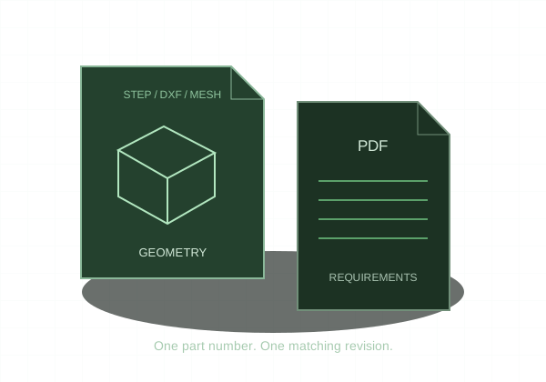
Make the drawing resolve ambiguity: units, revision, material, critical geometry, and acceptance requirements.
Identify the part
Include part number, revision, units, and a descriptive name. Match these to the STEP model. State material grade and condition rather than a broad family name when the distinction matters. A consistent title block helps keep the package traceable across future revisions.
Control functional features
Identify fitted diameters, mounting patterns, threads, and critical surfaces. Use datums that reflect how the part is located in the assembly. Add section or detail views where they clarify depth, wall thickness, or hidden geometry. Do not dimension a drill tip depth when the function needs a full-diameter bore depth.
Specify surface and secondary work
Define finish, edge treatment, inserts, or heat treatment only where required. Coatings may change fit and thread behavior. Special inspection reports and material documentation need an explicit scope. A material label does not automatically include certificates.
Run a consistency check
Compare every special callout with the model. Remove obsolete dimensions and conflicting general notes. Export a readable PDF and confirm that text and linework remain legible. Keep the accepted drawing package with the order so repeat parts have an unambiguous reference.