 Custom parts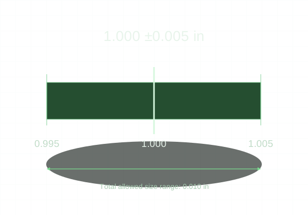
Start with what must assemble or move correctly, then assign tolerance to the features that control that behavior.
Nominal dimensions and limits
A nominal dimension is the target size. A tolerance defines its allowed variation. For example, 1.000 ±0.005 inch permits 0.995 through 1.005 inch. The total tolerance band is 0.010 inch, not 0.005 inch. Units and decimal presentation should be consistent across the drawing.
Fit is a relationship between parts
A shaft and hole must be considered together. Illustratively, a hole of 10.00–10.03 mm and a shaft of 9.95–9.98 mm produce clearance from 0.02 to 0.08 mm. Those example limits demonstrate arithmetic, not a recommended bearing or sliding fit for every application.
Size does not control everything
Flatness, perpendicularity, position, and runout describe geometric relationships that size limits alone may not control. Datum references establish how the part is located for evaluation. Use geometric tolerancing when it communicates the real function, with a consistent drawing standard.
Avoid tightening everything
Tightening every dimension can add machining, inspection, and rejection risk without helping function. Keep noncritical profiles at a suitable general tolerance and target the actual interfaces. KRC’s standard CNC dimensional tolerance is ±0.005 inch; tighter or geometric requirements must be explicitly defined in the accepted scope.