 Custom parts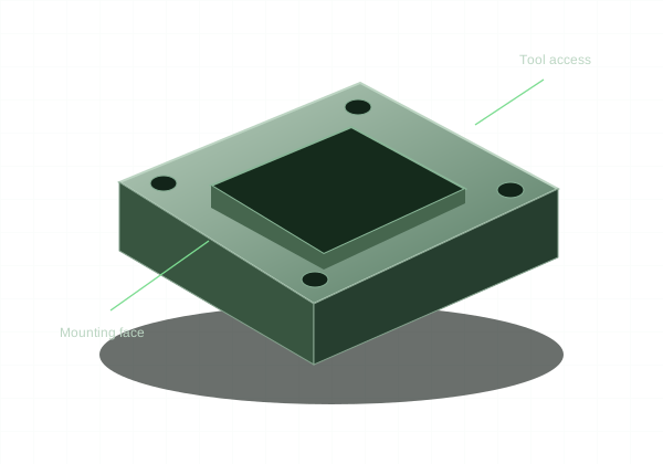
Define the mating surfaces first, then make the rest of the part easy to manufacture and assemble.
Part and process opportunities
Adapter plates, bearing-related housings, spacers, fixture blocks, and mounting brackets are common custom geometries. CNC milling and turning can serve different portions of the assembly. A part drawing should distinguish purchased hardware interfaces from custom features.
Design the interface
Use datums based on the actual mounting scheme. Avoid tolerance stacks that locate a critical axis through several loosely controlled parts. Design clearance for assembly tools, fastener heads, and component replacement. A machinable part is not useful if it cannot be installed.
Plan for the real use
Keep wear components separate where practical and use revision-controlled service part numbers. If a replacement must fit an installed machine, record the accepted interface dimensions. Do not assume a legacy part photograph fully defines the geometry.
Prepare a clear manufacturing package
Use a model that represents the intended part, a matching drawing for functional requirements, and a defined material and quantity. Choose the online process for supported configurations. Larger batches, unlisted materials, and special requirements follow custom RFQ. Industry examples describe possible uses; they are not evidence of certification or a past customer relationship.