 Custom parts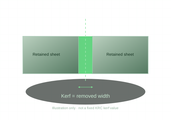
Every entity should represent an intended manufacturing path. Remove the rest before export.
Use full-size planar geometry
Create the profile in a single plane at 1:1 scale. Verify source units and one known dimension after export. A DXF can open successfully and still be the wrong size. For asymmetric parts, check whether the exported view has mirrored the intended orientation.
Close the contours
Connect endpoints so each perimeter forms a complete loop. Tiny gaps and duplicate segments can confuse profile detection. Remove overlaps and short stray lines. Keep circles as clean circles where practical instead of approximating them with unnecessary fragments.
Remove drawing information
Delete dimensions, center marks, hatching, borders, notes, and unrelated sketches from the cut file. Convert required lettering into suitable manufacturing geometry. Closed letter centers need bridges if they must remain attached to a through-cut stencil.
Check what will remain
Look at the material that survives the cut, not just the paths. Narrow webs between holes, isolated islands, and tiny tabs may be fragile. Make fit allowances deliberately and avoid adding an assumed kerf offset unless the manufacturing compensation convention has been defined.