 Custom parts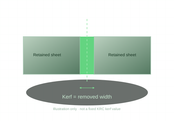
A cut path has width. That width must be considered once, consistently, in the manufacturing workflow.
A line becomes a slot
The CAD profile is an ideal line, but the laser removes material around a path. On an uncompensated outside contour, that can reduce the retained part. On an uncompensated hole contour, it can enlarge the opening. The sign of the effect depends on which side of the cut is retained.
Compensation moves the path
A manufacturing toolpath can offset from the nominal edge to account for cut width. In a simplified example, a 0.20 mm kerf corresponds to a 0.10 mm half-width offset. That number is only an illustration, not KRC’s published kerf or a recommended file adjustment.
The cut is material dependent
Material, sheet thickness, focus, and settings change the result. Edge taper also means the top and bottom of a cut can differ. A joint that fits in thin acrylic may not behave the same way in thicker plywood, even with the same nominal contour.
Design the fit before cutting
Define whether a tab should slide, press, or allow adhesive. Account for actual sheet thickness as well as profile size. Keep standard uploads at nominal geometry unless a compensation convention is explicitly defined; do not add a guessed kerf allowance and then apply it again in production.