 Custom parts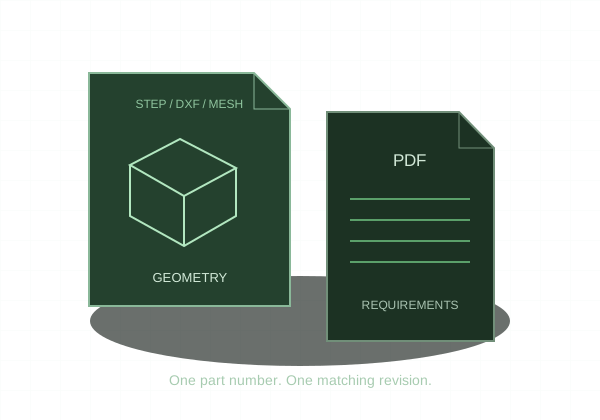
Export the intended component as STEP, then reopen the file to verify one solid body and the correct dimensions.
1. Prepare the design
Open the final design and save the intended revision. Ensure the part is a solid body rather than only surfaces or a mesh. For an assembly, isolate the component intended for this part order. Do not assume that a screenshot of visible geometry proves what an export will contain.
2. Export the geometry
Use File → Export and choose STEP (*.step or *.stp) from the available types. Where component export is available, exporting the selected component helps avoid unrelated assembly bodies. Set the file name and destination, then complete the export. Menu wording and availability can vary with Fusion version and document type.
3. Reopen and inspect
Import the exported STEP into a new document or a suitable CAD viewer. Verify the intended body, overall dimensions, and key features. Confirm that hidden or unrelated components were not included. Exporting from the source solid is preferable to converting an already faceted STL.
4. Prepare the drawing package
For CNC, pair the STEP with a PDF whenever threads, tolerances, fits, or finish need definition. Use the same part number and revision in both filenames. In KRC’s quote viewer, verify the final geometry and size again before selecting material and quantity.
Autodesk: export a CAD design