 Custom parts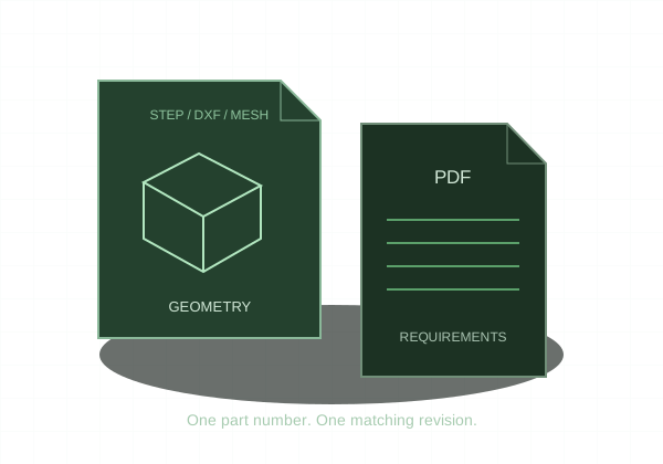
Use STEP for the CNC quote. Use STEP, STL, or 3MF for printing, and verify dimensions after export.
STEP preserves CAD geometry
STEP is a neutral exchange format for CAD surfaces and solids. Cylinders and other analytic geometry can remain mathematically defined rather than becoming visible facets. It is useful for machining workflows, but it does not necessarily carry the original feature history or every drawing requirement.
STL approximates the surface
STL describes triangles. Export resolution controls how closely that mesh follows the original shape. A coarse mesh can visibly flatten round surfaces; an excessively dense mesh can make the file difficult to handle without meaningful benefit. STL does not reliably define units.
Converting is not renaming
Changing .stl to .step does not create a CAD solid. A mesh-to-solid conversion may preserve all of the original facets rather than recovering exact cylinders and planes. When the original CAD is available, export STEP directly from it for machining.
KRC’s upload choices
The CNC quote accepts STEP/STP and an optional PDF drawing. The printing quote accepts STEP/STP, STL, and 3MF. Laser cutting uses DXF instead of either 3D format. Reopen an export and check a known dimension, body count, and intended shape before uploading.