 Custom parts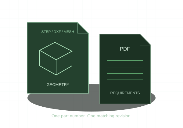
Save the intended part configuration as STEP and inspect the exported geometry before using it for a quote.
1. Select the right configuration
Open the part and activate the configuration that represents the required manufactured item. Rebuild the model and resolve errors. Check suppressed features, body count, and units. If starting from an assembly, identify the individual part needed for the order.
2. Save a STEP copy
Choose File → Save As and select STEP in the file-type list. Use the available export options to export solid geometry and review the selected STEP format and coordinate system where relevant. Save a separate copy with a clear part number and revision; preserve the native design file for future editing.
3. Check the neutral file
Open the STEP in a new document or CAD viewer. Verify that it contains the intended solid rather than an assembly, surfaces only, or an unintended subset of faces. Compare overall dimensions and critical geometry with the source. Export options can differ by software version.
4. Keep requirements with the model
A STEP export does not replace a controlled PDF drawing. Cosmetic thread features and visual appearances are not a reliable manufacturing specification. Add thread callouts, tolerances, material condition, and finish requirements to the drawing, with the same revision as the exported model.
SOLIDWORKS: STEP export options