 Custom parts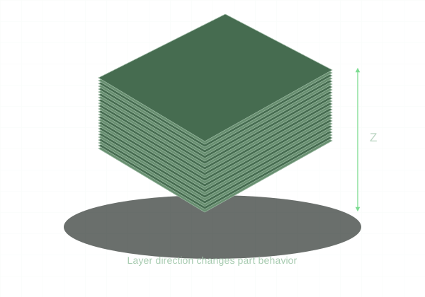
Give every feature a printable cross-section and a realistic load path. A watertight mesh is necessary, but does not prove manufacturability.
Make a valid model
Use a closed solid or a closed mesh with consistent face orientation. Remove accidental floating shells, self-intersections, and zero-thickness surfaces. STL files need a confirmed unit scale. Reopen exported files and compare overall dimensions before upload.
Walls and features
The current quoting configuration uses three standard walls and a nominal 0.2 mm layer height. That is a build configuration, not a universal minimum wall or dimensional tolerance. Design thin features with enough room for stable toolpaths. Fine embossed text and knife edges may not resolve as modeled.
Overhangs and supports
Unsupported downward-facing surfaces may need supports. Leave a path to remove those supports. Small holes, hidden internal roofs, and deep cavities can be difficult to clean. A chamfered transition can sometimes print more cleanly than a broad unsupported horizontal ledge.
Fit and load direction
Leave clearance between mating parts and use representative test features when fit is important. Strength varies with direction because the part is built in layers. Infill percentage alone does not establish load capacity; walls, orientation, geometry, and material also matter. KRC selects the final orientation and supports during production review.