 Custom parts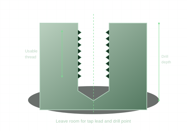
Separate the strength requirement of the joint from the amount of thread that is convenient to draw.
Write a complete callout
Identify system, nominal size, pitch, and thread depth. A metric callout such as M6 × 1 is not equivalent to a fractional-inch thread. Include fit class or handedness when those requirements differ from an ordinary default. A drawing should identify exactly which holes receive each thread.
Leave room below full threads
In a blind hole, the tap lead and drill point take up depth beyond the usable full thread. Define usable thread depth and drill depth separately when critical. Check the remaining wall below the drilled hole so it does not unintentionally break through or leave a fragile floor.
Engagement depends on materials
The required engagement changes with fastener strength, parent material, and loading. A commonly repeated multiple of diameter is only a starting heuristic, not a universal design rule. Longer threads do not fix insufficient wall thickness or a weak load path around the boss.
Consider inserts deliberately
Repeated assembly or high loads in plastic and softer metals may justify a thread insert. The insert type determines the receiving hole and installation requirements. Model and specify the actual insert system; a generic threaded cylinder does not define an insert-ready feature.